|
|
Multiposition Synthetic Aperture Radar (MPSAR) Alexander V Ksendzuk |
| Main Page |
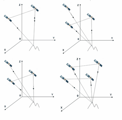
6. Multiposition SAR interferometer. Synthetic aperture radar interferometer uses for three-dimensional information extraction by using the phase (phase difference if be exact) as an information source. Usually interferometer is a SAR with two antennas (single-pass interferometer) or SAR with a single antenna, which measures altitude by means of repeat pass measurements. In this section considered multiposition SAR interferometer (MPInSAR) ¢ generally it consists of single interferometers inside multiposition SAR, possible spatial configuration of these single InSAR in multiposition system are presented in Figure 6.1.
Figure 6.1. Single interferometers inside multiposition SAR interferometer. Note that single-pass and two-pass interferometers are a particular case of the considered multiposition SAR. Therefore all presented methods and algorithms may be easily ōprojectedö to SAR interferometers.
|
| Signal Model | |
| Geometry | |
| Optimal Signal Processing | |
| Object detection | |
| Multiposition SAR interferometer | |
| Pseudonoise signals in remote sensing systems | |
| Pseudo-passive SAR | |
| Remote sensing systems modeling principles | |
| About Author | |
| Links | |
|
Below we consider some principal aspects of the multiposition SAR: scattered signal model, optimal signal processing algorithms, phase unwrapping algorithms, errors in the interferograms, secondary processing algorithms and modelling of the multiposition interferometer.
6.1. Signal model in single interferometer inside multiposition interferometric SAR.
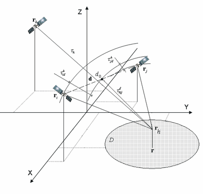
Consider interferometer with synthetic aperture, which consists of two receivers and one transmitter (other cases such as 1 transmitter-1 receiver, 2 transmitters-1 receiver, 2 transmitters may be easy obtained from the derived equation). Spatial configuration presented in Figure 6.2.
Figure 6.2. Single interferometer spatial configuration.
Vector of the received signals we will write as follows
where dot
in the uppercase
Signals, received in spatially
separated antennas will be different due to different way path. This means that
in general case parameters
To simplify
processing algorithm we will suppose that only time delay difference depends on
altitude
For the
tree-elements interferometer base will be vector
Time delays transmitter ¢ i th receiver and transmitter ¢ j thö receiver
can be modified by introducing time delay transmitter ¢ center of the base
Function
Signal in virtual SAR ōk
th transmitter ¢ center of the base
In most cases difference of the complex envelope time delay is inessential, in this case signal model may be transformed to
where
Functions
Input signal in the receivers we describe as addition of the scattered from the surface signal and noise, which approximate by Gaussian stochastic process with constant spectral density.
6.2. Optimal processing algorithm for the functionally-determined and stochastic surface models. For the functionally-deterministic model of the surface (see Section 2 Signal Model for detail about functionally-determined and stochastic surface models) scattered signal will be deterministic and probability functional of the input process will be
where only first statistical
moment of the input vector (average of the
When scattered from the surface signal considered as stochastic process (see Section 2 Signal Model for detail about functionally-determied and stochastic surface models)
where correlation function of the
input process When we solve equation of the optimal phase difference estimaton from the presented above signal models we will achieve optimal estimation algorithms for functionally-determined model of the signal scattered from the surface
for stochastic signal model of the signal scattered from the surface
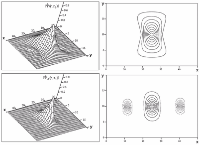
These algorithms involves aperture synthesis for both received signals (in different antennas or in different paths in case of monostatic InSAR) and further multiplication, which allow to find interferogram - dependence of the phase difference of the received signals Δφ as the function of the surface coordinates. Processing results contains radar cross-section (or if me exact ¢ estimation of the radar cross-section) as well. Space ambiguity function of the interferometer is multiplication of the space ambiguity function of the SAR (see Figure 6.3.) and ambiguity in phase (spatial harmonic). Overall spatial ambiguity function shows response of the interferometer for one spatial point with given altitude (or function which shows what spatial points which participate in signal return, which we refers to one-point signal), Figure 6.4.
Figure 6.3. Space ambiguity functions (point target response) in SAR for the optimal processing algorithms which consider scattered from the surface signal as functionally-determined (up) and stochastic (down).
Figure 6.3. Space ambiguity functions (point target response) in interferometric SAR for the optimal processing algorithms which consider scattered from the surface signal as functionally-determined (up) and stochastic (down).
As we can see from the above results when we take into account stochastic nature of the scattered from the surface signal we achieve narrower space ambiguity function. This leads to more accurate measurements of the altitude and radar cross-section.
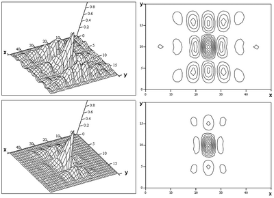
6.3. Phase unwrapping. Estimated phase difference distorted by noise. Usually this spatial noise has complicated impact (is not a normal process and canÆt be described as additive). Presence of the noise requires secondary processing (in simplest form is smoothing of the interferogram which contains noise). We propose to use method which has as input spatial functions ¢ non-smoothed interferogram, RCS, squared RCS estimated by interferometer and produces result ¢ interferogram with low noise. This method takes into account peculiarities of the primary processing as well as pecularities of the spatial configuration and allows to eliminate most of the errors in interferogram. We compare result of the unwrapped interferogram estimation in case when scattered signal was non-gaussian non-stationary stochastic process. results of the interferogram reconstruction (cross-section in azimuth) are shown in Figure 6.4.
Figure 6.4. Errors of the unwrapped phase difference estimation without secondary processing (up) with secondary processing due to proposed method.
Error elimination in case of the proposed secondary processing method leads to more accurate phase estimation after phase unwrapping.
In interferometric SAR we estimate
ambiguous function from the phase (arcsin(sin)for
example). The problem is to find unambiguous values. Moreover, when altitude
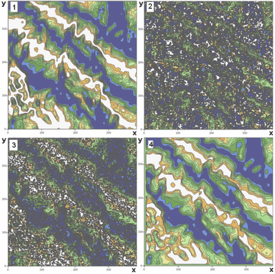
"jump" and cause phase change on Many investigators find own solution of this problem for different model of the interferogram, including different noise model. Here we extend the method of the least squares into multiposition interferometer. Results are shown below in the figure 6.5.
Figure 6.5. Modelling results of the altitude estimation 1-original altitude behaviour 2-estimated phase difference 3-phase difference after proposed secondary processing 4-.result of the altitude estimation
Conclusion. Significant advantages of the multiposition interferometric SAR is the possibility to accurate phase difference estimation, possibility to avoid classic ratio "ambiguity interval-estimation accuracy" and possibility to estimate altitude with high spatial resolution, high accuracy and increased unambiguity measurements interval. Proposed primary and secondary processing algorithms allow to eliminate noise, to estimate phase difference and radar cross-section with high accuracy and high spatial resolution. Analytic and modelling investigations prove higher quality of the proposed system in comparison with traditional interferometers with Synthetic aperture. |


|
C(c) Alexander V Ksendzuk |
